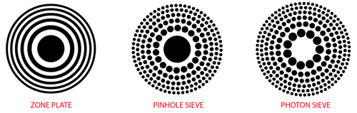
How to Make a Zone Plate, Photon Sieve or Pinhole Sieve
By Guillermo Peñate
Use the following tools and instructions to make your own zone plate, photon sieve or pinhole sieve. The tools and instructions are included in the zip file below. You will also need a high contrast B&W film and a high contrast film developer.
Download: http://www.pinholeday.org/docs/Zone_Plate_and_Sieves/zp&sieves-1.zip
Once you have downloaded and unzipped the file, follow these instructions:
- Decide which type of "lens" you want to print: Zone Plate, Pinhole Sieve or Photon Sieve.
- Using a text editor, like Microsoft's Notepad or equivalent, open the corresponding PostScript file (zoneplate.ps, pinholesieve.ps or photonsieve.ps).
- Change the parameter as indicated in the Postscript code. For instance, to change the focal length of
the "lens" to 80mm, you will change the number in the following line:
/F 75 def % change the number to whatever focal length in mm you want
to/F 80 def % change the number to whatever focal length in mm you want
Note that 75 is the value the file has after being downloaded, once you have changed it and if you save the edited file onto itself, it will keep that new number until you change it again. Feel free experimenting changing the other values as indicated in the Postscript file itself. - Save the *.ps file, I suggest you keep the original file intact and save your modified file with a different name to something meaningful, for instance: ZP80mm64.5.ps meaning Zone Plate 80mm f/64 +1/2 stops.
- Print your modified file.
You will need a program capable of printing Postscript files. I used PDFCreator, this program takes the *.ps file and convert it to PDF, that you can easily print. PDFCreator is free. Photoshop is also capable of printing *.ps files. I have also been told that a Mac computer recognizes postscript (*.ps) files without the need of any extra application.
- Do not scale down or up when printing the file, otherwise the printed "lens" will not have the correct size.
- At the bottom of the printed "lens" there is some self explanatory information. For your convenience, the distance you should place your SLR camera from the printed "lens" is indicated (in millimeters) as: "Distance to SLR's lens".
- Place your SLR at the same height of your printed "lens", and the film plane of the SLR parallel to
this printed "lens".
- Some SLRs, particularly those with "spot metering capabilities" have in their viewfinder a circle that indicates
the spot meter area:
This spot meter circle has a diameter that for each camera model should be indicated in its User's Guide Manual. We could use a compass to draw a circle on a piece of paper that has a diameter equal to the diameter of the spot meter circle in the viewfinder times the magnification used to print the "lens" and then place the camera at a distance such that the spot meter circle on the view finder overlaps it exactly. For example, in a Nikon F801s, also known as N8008s, the spot meter circle is 3.5mm in diameter, if we have used 30 as the magnification to print the "lens", we would need to draw a circle 105mm in diameter (3.5x30), place this circle on the same place we would later place the printed "lens" and make the spot meter circle in the viewfinder match exactly this 105mm circle.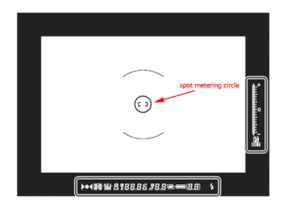
- Take a photo of each plate you make and develop the film to make the negative (reversed) image. Use the highest contrast B&W film possible and process it using equally high contrast chemicals. After developing the film, cut each individual negative frame and mount it in the camera with the matching focal length.
Copyright © 2026 Guillermo Peñate • File was last modified: April 19 2026 10:55:45.